Material thickness
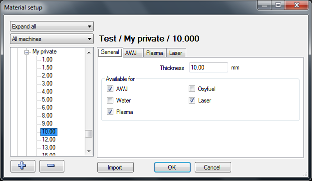
Add or delete thickness
If a thickness is selected in the list then add a new thickness or delete an existing thickness by clicking on the "plus" or "minus" buttons.

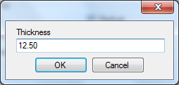
Press the "plus" button and enter the thickness "12.50".
Press the "minus" button to delete.
General
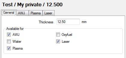
On the general tab change the thickness and control what machine types can be used for this specific material.
AWJ
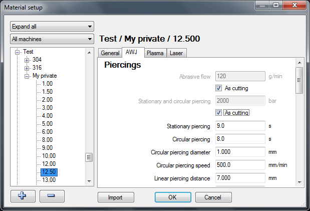
Piercings
IGEMS supports different methods to pierce through material.
Individual piercing parameters
To use a different amount of abrasive or a different pressure for the piercing enter values here:
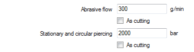
Check the two boxes "As cutting" to not use any special values. When cutting brittle material, piercing at a lower pressure is often needed.
Stationary piercing

The jet will stay in the same position during the entire pierce.
The value is the length of time in seconds that the jet will be on. This piercing method works best on very thin material.
Circular piercing
The jet goes around a small circle during the entire pierce. This is one of the most common methods of piercing on an AWJ machine and works well on thin and thick material.

Circular piercing
This controls the piercing time it takes for the jet to cut through the material.
Circular piercing diameter
This is the movement diameter. The diameter in the material will be this value plus the diameter of the jet.
Circular piercing speed
This value is in mm/min. The faster the speed the more number of revolutions is used.
Note! If the diameter is too small, or the speed too high, then the centrifugal acceleration may exceed the acceleration limits. In this case the text will change to red.
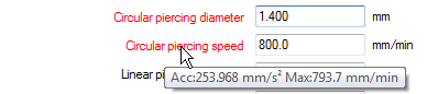
Hold the pointer on the text to see a tooltip with information about the actual accelerations. The maximum acceleration is set in the machine setup.
Linear piercing
The jet makes a linear movement during the entire piercing. If the distance is longer that the length of the lead then the movement will go back and forth until the specified distance is reached.
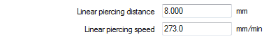
Linear piercing distance
This is the length needed for the piercing to be able to cut through the material.
Linear piercing speed
This is the speed that is used for the piercing.
Overcut distance
This value is used as the default overcut distance when the cutting starts directly on the geometry (Lind lead).

This value controls the length of the overlapped cut.
Dynamic leads
Dynamic leads are used to have the piercing position as far away as possible from the geometry. It is a nice feature when cutting material that often breaks on the bottom side during the piercing.

Dynamic lead min length
This should be the shortest acceptable lead length for this material.
Dynamic lead max length
Set this value to the maximum required lead length. While safer to have a longer lead this takes time to cut.
Cutting
The information in this area controls the thickness depending information for the cutting process.
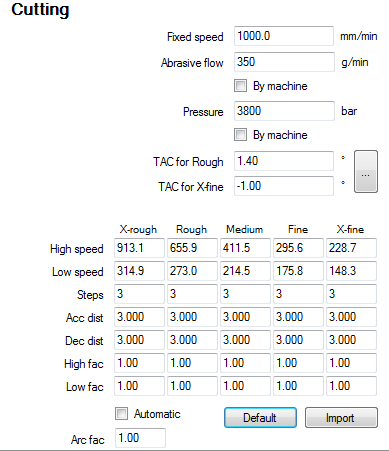
Fixed speed
This value is used when "Fixed speed" is selected in the Machine setup. When using fixed speed there is no possibility to use qualities or speed ramping. The value is only used on an AWJ machine without using the "AWJ" module.

Individual cutting parameters
It may be an advantage for certain materials to use other cutting parameters than the machine uses as standard. If that case, set up the individual cutting parameters here.

Abrasive flow
This controls the amount of abrasive. To use the standard amount of abrasive check the box "By machine".
Pressure
This value controls the pressure. To use the standard pressure for cutting check the box "By machine".
Taper angle control
Depending on material properties and cutting parameters the cut through the material is not always 100% straight.
By using the Taper Angle Control feature manually adjust the inclination of the nozzle. IGEMS does not use any mathematic formula to calculate the taper. Make a test cut to adjust the TAC parameters.
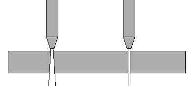
Cut a small test part without TAC using cutting quality Rough and X-Fine.
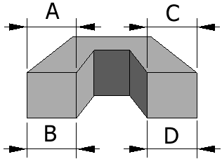
Measure the Rough side A and B. Measure the X-Fine side C and D.
Start the "TAC Calculator" by clicking on the button.
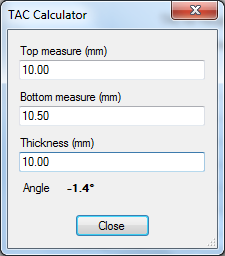
The TAC Calculator calculates the angles. If the measurements are smaller on the bottom side on an outside geometry then the angles are negative else positive.

TAC for rough
Enter the angle for the "rough" measurement.
TAC for x-fine
Enter the angle for the "X-fine" measurements.
Note! To use the "TAC" option a standard CNC machine is needed with at least 4 or 5-axes controlled by the CNC and the nozzle can be tilted in different directions.
Automatic speed optimizing
The automatic speed optimizing adjusts the cutting speed depending on cutting parameters, material properties and geometry to be cut. Straight lines and large arcs are cut with a higher speed than sharp corners or small arcs. The automatic speed optimizing uses another algorithm than earlier versions of IGEMS. The speeds are therefore not the same as before, but still divided into five qualities.
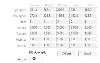
At IGEMS R&D Center, we are constantly updating and fine-tuning cutting parameters. Updating IGEMS may also update cutting speed parameters. The automatic speed optimizing is activated when the checkbox "Automatic" is checked.
Manual speed optimizing
The manual speed optimizing uses the same formulas as IGEMS R8 and R9. Use this option to fine-tune parameters. The values are not changed in an update of IGEMS.
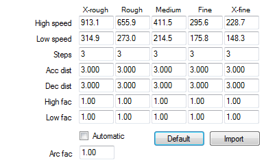
The following parameters can be adjusted:
High speed
This speed is used by straight lines and arc radius larger than the thickness of the material.
Low speed
The low speed is dependent on the geometry. The sharper the corner or the smaller radius size of an arc the lower speed will be used. The speed will never be lower than this value.
Steps
This value is only used if when using the ramping method "Speed interpolation by CNC-file" (defined in the machine setup).
Acceleration distance
This is the total length of all speed increasing steps when the speed changes from low to high speed.
Decelaration distance
This is the total length of all speed decreasing steps when the speed changes from high to low speed.
High speed factor
The speed is calculated by known parameters such as: Machinability, Pressure, Orifice size, Abrasive quality, Amount of abrasive, Nozzle size, Cutting quality and the thickness of the material. If the actual high speed isaccording to this algorithm then the height factor is 1.00. If the high speed is changed it will also change the high speed factor.
Low speed factor
This factor does the same as "High speed factor" but for the "Low speed" values.
Arc factor

This value controls the cutting speed in the arcs. If this value is set to a higher value then the small arcs will use a higher speed. Normal value is 1.00
Default

Press this button to reset the values to default. This will change all values on this material according to the algorithm.
Import
The database in R10 is different from previous versions. To use old values in IGEMS R10 use the import function.
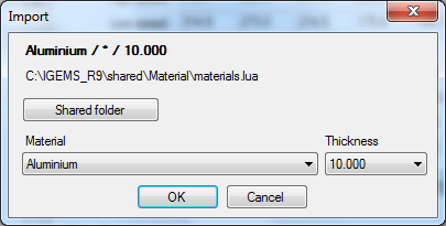
Shared folder
When using this command for the first time, select the location of the shared folder. IGEMS R10 will then remember this location.
Material and thickness
Be sure to use the same material and thicknesses as in IGEMS R10.
Repeat these steps for every material imported to IGEMS R10.
Nesting
Some nesting parameters can be saved in the material database.
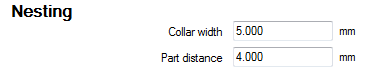
Collar width
This value sets the default value used when creating new sheets.
Part distance
This value sets the default value for the part distance. The value is used in the "Nesting" commands.
Various

The "Technology", "Options" and "User" settings are read by the postprocessor for handling different equipment or functions in the postprocessor.
Plasma, Oxyfuel and Laser settings
IGEMS is developed for Abrasive Water Jet Cutting, but also supports other machine types such as Plasma, Oxyfuel and Laser machines. These machines have similar inputs.