Select setup
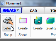
When any "CAM" command is started that needs information from the "Machine" or the "Material" then this dialog box is automatically shown.
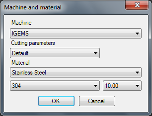
To select this information at the beginning of the process gives IGEMS possibilities to suggest the best default values. Select another machine or material at any time.
The actual filename and selections are shown at IGEMS title row at the top of the program and at the Drawing File Selector at the lower right corner of the screen.
Table layout
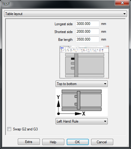
Machine orientation on the screen
In IGEMS R10 the user defines the machine coordinate system independent on how the coordinate system is defined in IGEMS. Since new computer screens are much wider now it is recommend that the machine layout in IGEMS is defined so that the long side of the machine is rotated as the long side of the screen.
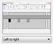
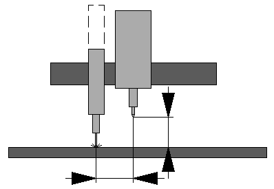
The black rectangle on the picture defines the first tool.
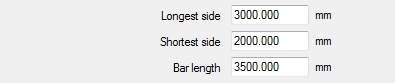
Width
Enter the length of the side of the machine that is oriented horizontal on the screen.
Height
Enter the length of the side of the machine that is oriented vertical on the screen.
Bar lenght
This value should be the maximum movement from the left tool in the most left position to the right tool in the most right position.

This value is used by the simulation functionality in the postprocessing.
All the settings in the Table layout should now describe the fundamental dimensions of the machine.
Coordinate system

In IGEMS R10 there is no relation between the CAD coordinate system and the Machine coordinate system. Select the coordinate system according to the machine layout on the screen.
Swap G2 and G3
According to chosen coordinate system 0-7 the G2/G3 Arc directions are swapped automatically. To manually change the direction, activate this function
Cutting tools
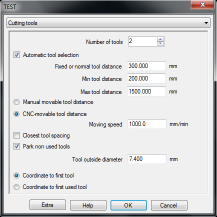
If the machine is equipped with more than one tool, then the postprocessor needs to know how to handle the equipment

Enter the number of cutting tools. Do not include marking and drilling utilities.
Automatic tool selection

If a job handles different tools, the postprocessor needs to know how to instruct the machine as to which tool is on and off. Old machines may only have manual switches to select tools. If active tools can be changed by the CNC-file then activate this setting.
Hanlde the distance between tools
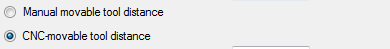
Fixed or normal distance
This value is used as default distance in the "Tool setup" command and in "Auto nest". Using a fixed distance is important for a machine that does not have the ability to change the tool distance.
Min tool distance
This value is used by the dynamic tool distance function in "Auto nest". "Auto nest" never uses a smaller distance than this value.
Max tool distance
This value is also used by the dynamic tool distance function in "Auto nest". "Auto nest" never uses a larger distance than this value.
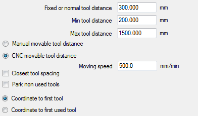
Closest tools spacing
This settings controls how non-used tools are packed on the cross beam.
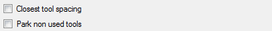
If not activated then all tools on the beam will have the same distances.
In this example T2 and T3 are used for cutting and the distance should be 500mm.

Park non-used tools
Some machine constructions put non-used tools in a parking position. This means that they are not moved on the cross beam if they are not in use. This information is used to make a more correct simulation.

Calculate tool offsets
When using Tool 1 then the coordinates will always be calculated to this tool. When using another tool then this setting controls how the coordinates should be given.
Example:
When using tool number 3 only and the distance between each tool is 300mm the position is X1000:
Coordinates to first tool gives the value in the CNC-file: 1000-300-300=X400
Coordinates to first used tools gives the value in the CNC-file: X1000
Tool outside diameter

This value is used in the "Tip up avoidance" feature in the "Order" command. It has no affect on the final CNC-file or the postprocessor.
Z axis control
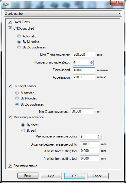
IGEMS R10 supports five different methods of controlling the Z-axis. Select all methods supported by the machine. In the "Strategy" command select which method to use depending on the actual material and working strategy.
Fixed Z-axis

Check this method if the machine cannot move the Z-axis from instructions in the CNC-file or if the cutting tool is to be in the same Z-axis position all time.
CNC-controlled
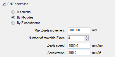
The CNC-controlled method has three options:
Automatic
This option is used if the tools go up and down with the same codes for cutting on and off. This means that the machine will always move the tool to the upper position defined by the "Max Z-axis movement" between each cut. The different settings in the strategy that control the lifting of the tools are disabled.
The reports calculate the time depending on the "Max Z-axis movement"," Z-axis speed" and "Acceleration".
M codes
Use this if separate M-codes are used to move the cutting equipment up and down. The strategy controls if the tool lifts between different operations or not. The user cannot control how much the tool lifts. The reports calculate the time depending of the "Max Z-axis movement"," Z-axis speed" and "Acceleration".
Z coordinates
Activate this if the machine supports movement with Z-coordinates. These settings allow the user to have different Z-axis values for different operations in the "Strategy" settings (Drilling, Marking, Pre-piercing and Cutting and movements between parts). The reports calculate the time based on all given information.
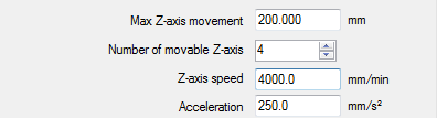
Max z-axis movement
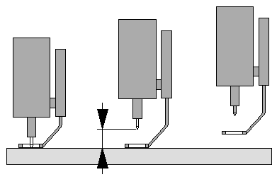
This is the limit setting for the Z-axis value. The value should be measured from the table surface up to the most upper position. To not over travel in Z, decrease this value by some millimeters.

The maximum Z-axis movement that is used by the machine is this value minus the material thickness.
Number of movable z-axis

It is possible to add more than one tool on each Z-axis. Picture 730 shows 6 cutting heads, but only two movable axes. If the number of tools and the number of Z-axis is different, there is a manual tool distance movement.
Z-axis speed
The Z-axis speed (axis up and down) is used in the CNC-file. It is also used by the simulation and the time calculation.
Acceleration
The acceleration for the Z-axis is used to get a more exact time calculation. It does not affect the CNC-file.
By height sensor
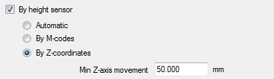
Activate this option if the machine has a Height sensor that controls the Z-axis.
This option has three choices:
Automatic
This option is used if the height sensor is activated and deactivated with the same codes for cutting on and off. This means that the machine will always move the tool to the upper position defined by the "Max Z-axis movement" between each cut. The different settings in the strategy that control the lifting of the tools are disabled. The reports calculate the time depending of the "Max Z-axis movement", "Z-axis speed" and "Acceleration".
M codes
This code is used if separate M-codes activate and deactivate the height sensor. The strategy controls if the height sensor is turned on and off between different operations. The user cannot control how much the tool lifts. The reports calculate the time depending of the "Max Z-axis movement", "Z-axis speed" and "Acceleration"
Z coordinates
Activate this if the height sensor can be used togheter with Z-coordinates. These settings allow the user to have different Z-axis values for different operations in the "Strategy" settings (Drilling, Marking, Pre-piercing and Cutting and movements between parts). The reports calculate the time based on all given information.
Min Z-axis movement
Set this value to the distance the Z-axis must move up before the sensor starts to lift up from the material.
Depending on the postprocessor this value is also used when the Z-axis is moved down.
Measuring in advance
This feature is mainly developed for 5-axis machines that cannot be equipped with a height sensor and when controlling the height during the cutting is needed.
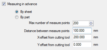
This option is used on a machine that has no height sensor to use during the cutting.
By sheet
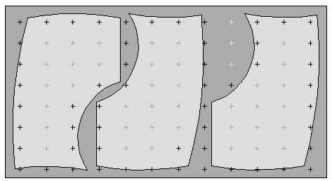
This method measures the whole sheet in advance. It only measures points that are close to the cutting geometry and that will be used by the cutting.
By part
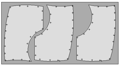
This method is a combination of measuring and cutting. It measures the geometry and then cuts the geometry; then it measures again and then cuts again, and so on.
Measure data
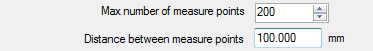
Max number of measure points
This value affects the size of the measuring grid when using the "By sheet" option. 200 points means a grid of 10x20 or 12x16 points, depending of the ratio of the sheet.
Note! The system only measures the points that are closest to the geometry.
Distance between measure points
This value sets up the maximum distance between measuring parts when using the "By part" option.
Offsets
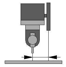
IGEMS can adjust distance from the measuring equipment to the cutting position. This is important to get the measurement or correct positions.
If these distances are controlled by the controller then set these values to zero.
Pneumatic stroke
Some machines are equipped with a "pneumatic stroke" that moves the cutting equipment very fast up and down.

The "pneumatic stroke" can be combined with all other measurement methods above.
Marking tools
Markings can be used in combinations with cutting. Marking is useful for identifications, bending lines, welding position and much more. The following options are available:
No marking tools
IGEMS will skip all marking information in the CNC-file. Use this for toolpath that contain markings but there is no marking equipment.
Use cutting tool as marking tool
This is the most common alternative that is used on water jet machines and lasers.
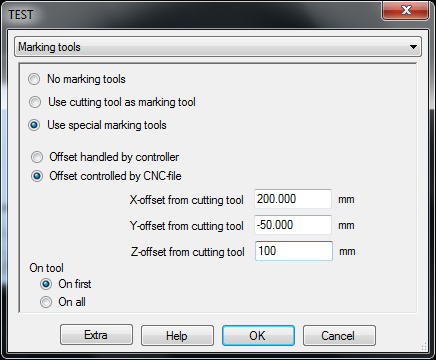
Use special marking tools
Use this option if the marking equipment does not use the cutting head as the marking tool. The marking equipment can be powder, inkjet, etc.
Offsets
Offset handled by controller
Use this option if the offset from the cutting head to the marking unit is handled by the controller.
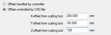
Offset controlled by the CNC-file
Use this option if the CNC-file should write information that handles the distance between the cutting head and the marking unit.

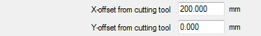
X-offset from cutting tool
Enter the value related to how the machine is oriented on the screen.
Y-offset from cutting tool
Enter the value related to how the machine is oriented on the screen.
Z-offset from cutting tool
Enter the Z-axis difference between the cutting tool and the marking equipment.
Drilling tool
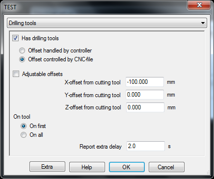
If the machine has drilling units then activate the checkbox "Has drilling tools".
Offset handled by controller
Use this option if the offset from the cutting head to the drilling unit is handled by the controller.
Offset controlled by the CNC-file
Use this option if the CNC-file should write information that handles the distance between the cutting head and the top off the drilling unit.
Adjustable offsets
If the drilling tools are adjustable, then it is important that the offsets can be adjusted easily. If this checkbox is activated then the offsets can also be adjusted from the "strategy" window. If not activated, then the offsets can only be changed from the "machine setup".
X-offset from cutting tool
Enter the value related to how the machine is oriented on the screen.
Y-offset from cutting tool
Enter the value related to how the machine is oriented on the screen.
Z-offset from cutting tool
Enter the Z-axis difference between the cutting tool and the marking equipment.
Location
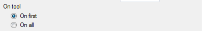
IGEMS supports drilling tools placed on all heads or one head. The single drilling tool can be located on an optional head.
Report extra delay

When calculating the drilling time IGEMS uses the information from different speeds related to the X, Y movement and the actual Z-axis options. The "Drilling delay" is used to fine-tune the estimated cutting time.
Speeds
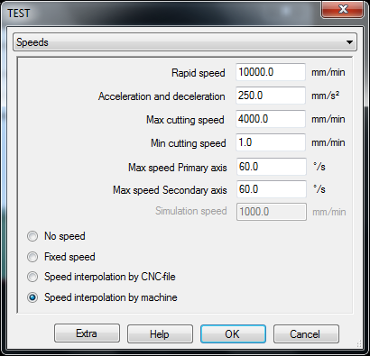
Rapid
To have a better estimation of the cutting time provide the rapid speed and the acceleration and deceleration parameters.
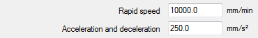
Rapid speed
Set the value of the rapid speed supported by the machine. The values entered here do not affect the final CNC file and is only used for calculations.
Acceleration and deceleration
If X and Y axis have different values, then use the smallest value of the two
Cutting speeed
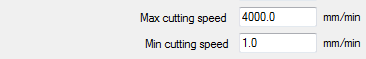
Max cutting speed
Set this value to the maximum cutting speed desired. If the database generates a faster speed then IGEMS reduces the speed to the "Max cutting speed" value.
Min cutting speed
If the database generates values that are too low then IGEMS will round up the speeds to this value.
Max speed for 5-axis heads

In IGEMS the primary axis is always called A and the secondary axis called B. The A and B speeds are calculated from the motion and the speeds of X and Y (A and B axis are slaves to the X and Y movements).
Kinematic constructions (when the primary axes are in vertical direction) may sometimes need extremely high rotation speed. By specifying the maximum A and B speed it is possible for IGEMS to calculate a XY speed that never exceeds the maximum speed for A and B.
Speed modes
IGEMS works with 4 different speed modes:
No speed
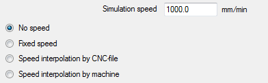
This mode is used when the CNC-controller calculates all speeds. IGEMS internally uses a speed called "Simulation speed". This speed is the same and never changes, no matter if material or cutting quality changes. IGEMS needs this speed to present reports and for making simulations.
Are there any disadvantages to calculating the speed in the controller?
Yes, you can't make cost estimations and other reports in advance.
Fixed speed
The "Fix speed" value can be stored on every thickness for every material in the material database. When this mode is selected IGEMS uses this speed. The speed will not change depending on the cutting quality.
Speed interpolation by CNC-file.
To obtain a good cutting result with a fast production then the cutting speed must be optimized for the material, thickness and the geometry. When speed optimizing is used IGEMS takes care of all speed optimizing. This gives a fast production, a very good cutting result and also gives correct cutting times, reports and simulations.

When using "speed optimizing" IGEMS controls all kind of speeds in the CNC-file.
To be able to have a smooth acceleration and deceleration linear and circular movements are split up into shorter movement, each movement changes the speed a little step.

To make a smooth acceleration the movements are divided into shorter steps. In the example above it will need 13 lines in the CNC-file to create this movement. More or less all controllers can use this method.
Speed interpolation by machine
Some controllers have a functionality to make it possible to interpolate with the speed.

IGEMS' technology for feed interpolation is working on Siemens FLIN/FNORM functions but other controllers provide similar functionality. The result will be smoother movements, shorter CNC-files, better cutting results and shorter cutting time.
Note! This speed mode is unusable if the machine does not support cutting speed interpolation.
Postprocessor
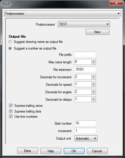
These settings handle the fundamentals in the postprocessing, such as naming the file and different formats.
Postprocessor selection
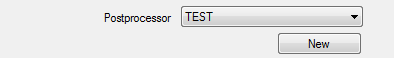
The postprocessor is an open text file written in ILISP syntax. The ILISP documentation has detailed information on how to change or develop postprocessors. To make a new postprocessor press the "New" button and enter a name of the new postprocessor.
Output file
The postprocessor creates a file that can be used by the CNC-machine. The settings below describe the rules for how the file can be named:
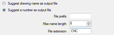
Suggest drawing name as output file
In this case IGEMS will suggest that the output file name will be the same name as the actual drawing. The extension of the file is defined below.
Suggest a number as output file
Many users want to have the output files named as a number (100.CNC, 101.CNC, 102.CNC). With this setting the actual number will be increased by one for every new output file created.
File prefix
Specify here if there should be any prefix added before the number.
Max name length
Specify longest acceptable file name.
Note! This controls only the name not the extension of the file.
File extension
This is the extension of the output file.
The following table describes the result of different settings:
| File prefix | Max name length | Number | Extension | Result |
|---|---|---|---|---|
| 8 | 100 | .CNC | 100.CNC | |
| P | 8 | 101 | .CNC | P101.CNC |
| P000000000 | 8 | 102 | .CNC | P0000102.CNC |
| P00 | 10 | 103 | P00103 | |
| 3 | 1010 | .CNC | 010.CNC | |
| 0 | 6 | 104 | .DNC | O104.DNC |
Add information where the CNC-file will be saved in the "Strategy" command.
Format
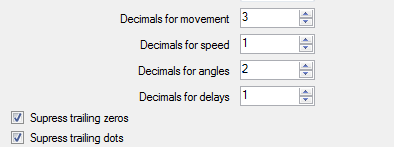
Decimals for movements
This setting controls how many decimals are used to present the movements in the output file. The value is generated by the (RTS 'value') function in the postprocessor.
Decimals for speed
This setting controls how many decimals are used to present the speed in the output file. The value is generated by the (RTF 'value') function in the postprocessor.
Decimals for angles
If using a 5-axis machine this value controls the number of decimals. The value is generated by the (ATS 'radian') function in the postprocessor.
Decimals for delays
This controls how many decimals are used for delays in the output file. The value is generated by the (RTT 'second') function in the postprocessor.

Suppress trailing zeros
If this checkbox is activated then all trailing zeros will be removed.
Example: 10.000 will be 10. and 10.100 will be 10.1.
Suppress trailing dots
This feature is only useful if "Suppress trailing zeros" is activated.
Example: 10.000 will be 10 and 10.100 will be 10.1.
Line numbers
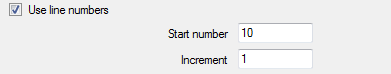
This option controls the ILISP function (NTXT). The function generates a text with increasing numbers.
Example: N10, N15, N20, N25 and so on. The numbers are used on many controllers. Check the box to control if the line numbers should be used. Set the start value and the increment.
Output units

By setting this to "Automatic" the output file is in the same units as the drawing. The output can also be set to Metric or Imperial. If this setting is different than the units on the drawing then IGEMS will scale the output dimensions.
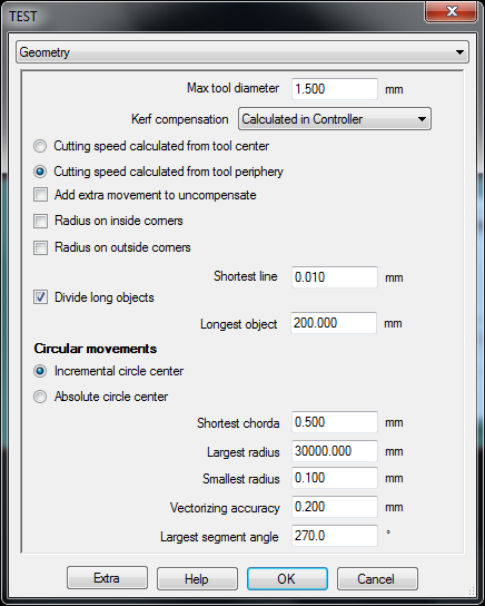
Geometry
Tool radius compensation
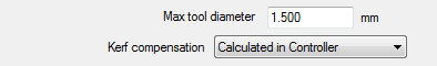
Max tool diameter
This is a very important setting that controls IGEMS geometry optimizing. The value should always be larger than the largest tool diameter used on the machine.
What will happen if this value is smaller?
The machine will stop with a contour error.
Kerf compensation
IGEMS supports three different options:
Calculated in IGEMS
With this option the toolpath is internally offset by IGEMS. The size of the compensation is the same as the Tool Radius (TR). There are no kerf instructions in the CNC-file (it will use G40 mode or similar).The coordinates in the CNC-file is the same as the movement of the machine. To change the measurements of the parts run the postprocessor again
Calculated in IGEMS and Controller
With this option the toolpath is internally offset by IGEMS. The size of the compensation is the same as the Tool Radius (TR). The postprocessor adds kerf instructions (G41, G42 or similar). The idea behind this is that IGEMS controls the major part of the kerf compensation (TR) and the machine controller adds a smaller kerf (K) just to fine-tune the measurements. This option makes it possible to adjust the size of the part without creating a new CNC-file.
Calculated in Controller
When using tool radius compensation Right or Left (G41 or G42) the coordinates in the CNC-file describe the size of the part (not the machine movement). The Kerf (K) will be added in the CNC-controller. This option makes it possible to adjust the size of the part without creating a new CNC-file.
Cutting speeds in circular movements
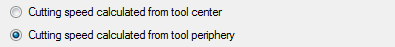
When the kerf is calculated in IGEMS the speed is always calculated from the tool center. When using tool compensation in the machine then the controller has two choices.
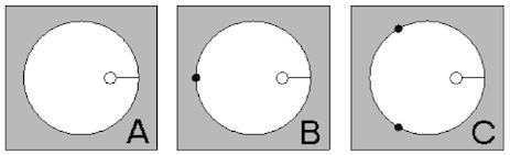
In the examples the hole has diameter 1.5 and the jet diameter 1.0.
In example A the programmed path speed is on the tool center point (dashed circle). In example B the programmed path speed is set to the work piece contour. This programmed path is three times longer.
To have an optimal result it is important for IGEMS to know which method the controller will use.
Cancel kerf compensation

Some controllers need to make an extra movement to cancel the kerf compensation. If this option is activated, then an extra movement will be added after the kerf compensation has been turned off. The length of the movement is the same as the tool diameter and the speed is the same as maximum cutting speed.
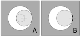
Corner radius
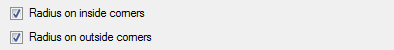
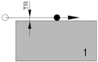
The following pictures show the center of the tool. When the kerf compensation is calculated in the machine then the machine will always make radius on outside corners:
No radius (example A)
Only use this solution when the kerf compensation is calculated in IGEMS.
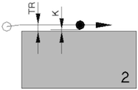
Radius on inside corner only (example B)
If the kerf is calculated in IGEMS then the inside radius size will be half of the difference between "Max tool diameter" and the actual tool diameter. If the kerf is calculated in the controller then the radius will be half of "Max tool diameter".
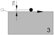
Radius on outside corner only (example C)
If the kerf is calculated in the controller then the machine will always make this arc. If the kerf is controlled in IGEMS then turn this radius on or off.
Radius on inside and outside (example D)
See example B and C
Which combination will give the best cutting result?
Example A: Do not use any radius on inside or outside.
What is the other alternative used for?
IGEMS supports many machines and some machines need the other options.
Remove short lines

Using very short lines in combination with using kerf compensation can sometimes cause geometry problems. Linear movements shorter than this value will be removed from the CNC-file.
Divide long objects

This feature splits up long lines or circular movements into shorter steps. It should be easier to restart the machine on a good position if the machine is stopped.
Edit sheet properties
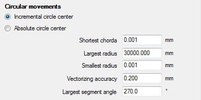
Circle center
The postprocessor gives the possibilities to hardcode one of these two options. If the machine supports both of these methods, then select which method to use.
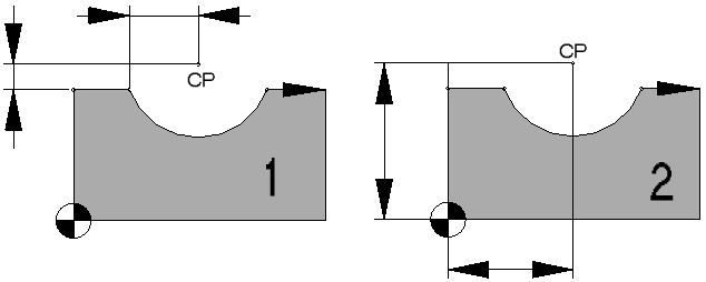
Example 1 describe the "Incremental circle center" and example 2 the "Absolute circle center".
On many controllers the circle center can be described by the radius. This method is also available in the postprocessor.
Shortest chord
Almost all CNC controllers are using the same G-code (G02 and G03) to describe an arc and a circle. If the distance from the start point to the end point is close then the machine will make a circle.
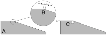
If (B) is a short arc then the machine may make an unwanted circle movement (C).
The value of the shortest chord must be high enough so no unwanted circles are created.
Chords that are too short will be replaced by a linear movement.
Largest radius
Enter the size of the largest arc or circle that is supported by the CNC-controller. If the radius is larger, then it will be vectorized.
Vectorizing accuracy
The differences between the original arc geometry and the lines will not exceed the vectorizing accuracy.
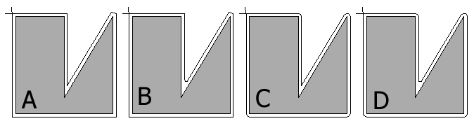
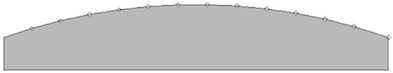
Largest segment angle
This value controls the largest segment angle that will be generated by the postprocessor. The value can be in range 1 to 360 degree. If the segment angle is larger then this value the arc will be divided into parts.
In the example (A) the value is set to 360 degrees and the circle movement is not divided. In example (B) the value is set to 180 degrees and in example (C) the value is set to 120 degrees.
5 axis kinematic
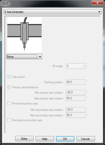
Set the choice to "None" if the machine does not a 5-axis cutting head.
The arrows describe the positive axis directions.
Supported 5 axis heads
IGEMS has an inbuilt kinematic model for most kinds of 5-axis cutting heads. Other constructions than below can be defined in the postprocessor.
Vertical-Horizontal
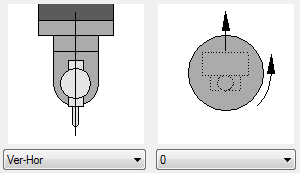
In this construction the primary rotation is vertical and the secondary horizontal. Set the zero rotation of the vertical axis as the layout and axis direction are defined on the screen.
Vertical-Tilted
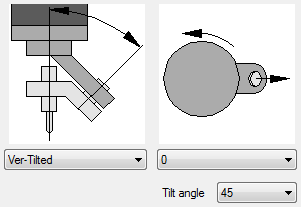
In this construction the primary rotation is vertical. The secondary angle can be set to 45 or 30. It is possible to define other angles in the postprocessor. Set the zero rotation of the vertical axis as the layout and axis direction are defined on the screen.
Tilted-Horizontal
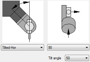
In this construction the primary axis is tilted and the second is horizontal. The tilt angle from vertical is 50 degree. Other tilt angles can be defined in the postprocessor. Set the direction of the primary axis as the layout and axis direction are defined on the screen.
I-HEAD
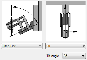
In this construction the primary axis is tilted and the second is horizontal. The tilt angle from vertical is 65 degree. Other tilt angles can be defined in the postprocessor. Set the direction of the primary axis as the layout and axis direction are defined on the screen.
Horizontal-Horizontal
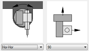
In this construction both axis are horizontal. Set the direction of the primary axis as the layout and axis direction are defined on the screen.
Other settings
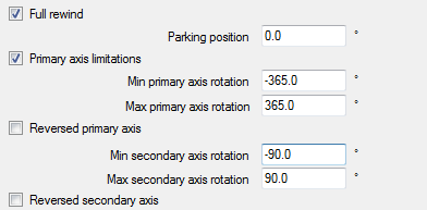
Full rewind
When the primary axis has rotation limits it may be necessary to make a rewind when the rotation reaches the limits. There are two options to make 360 degree or 180 degree rewind. Check "Full rewind" for 360 degrees.
Which is best?
This depends of how much you can rotate. Full rewind gives better re-position of the nozzle and gives best quality and accuracy.
Parking position

This setting is only important if the primary axis is vertical. It controls the angle the primary axis should be when in "parking position" (when it is not in use).
Primary axis
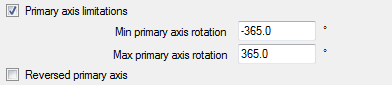
If the construction has rotation limits for the primary axis then activate the checkbox. Set the max and minimum rotations for the axis. The system will automatically generate a rewind if needed. The axis direction should always be given as "Right hand rules" as the layout and axis direction are defined on the screen.
Reverse direction
If the primary axis is defined in the opposite direction in the controller then activate this checkbox.
Secondary axis
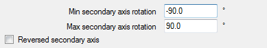
Enter the "minimum" and "maximum" angle for the secondary axis. If the axis direction is defined in opposite directions then check the "Reverse secondary axis".
Cutting equipment
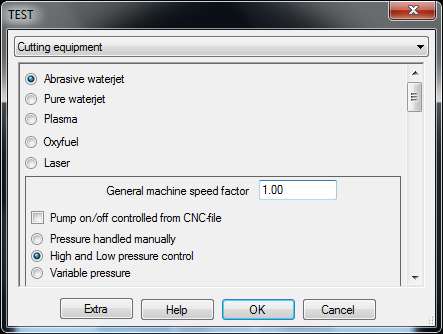
IGEMS is designed for Abrasive waterjet but also supports other kinds of cutting machines. Select what machine type the machine should be set up for.
Abrasive waterjet
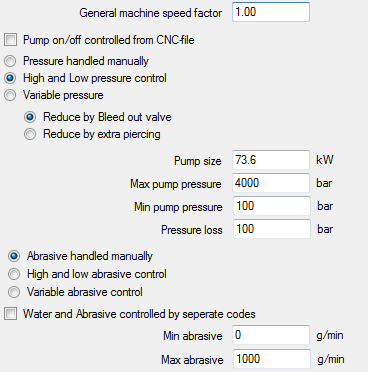
General machine speed factor
If it seems that all cutting values in the material setting are too low or too high then change them globally by
changing the "General machine speed factor".
The example below shows High speed and Low speed for Stainless steel 12mm.
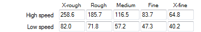
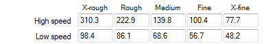
When the "General machine speed factor" is changed to 1.20 the speed will be increased by 20%.

The values below are for the same material and cutting parameters.
Why can't they all use the same speed factor?
There are many manufacturers of cutting equipment on the market and there is a big difference in qualities.
Pump and pressure setting
Pump on/off controlled from CNC-file
Check this option if the system can turn on or off the pump from the CNC file. It is possible to control whether or not this should done in the "strategy.
Pressure handled manually
If the system cannot change the pressure then the machine will stop and the operator can change pressure manually.
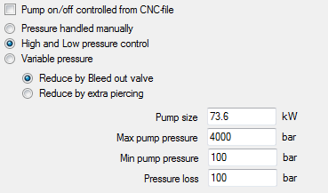
High and Low pressure control
Many systems have two levels of pressure - High and Low. Check this option if the system can switch between these two by using M-codes.
Variable pressure
Select this option if the system can handle the pressure steeples.
Reduce pressure

Check this option if the system reduces the pressure by a "Bleed out valve".
If the system does not have any equipment to release the pressure then it is possible to reduce the pressure by making an extra piercing. The extra piercing will be done in an already pierced position.
Pump size
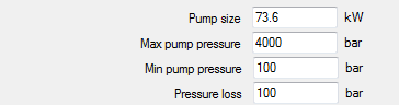
This refers to the motor size; the value is not used for the moment.
Max pump pressure
Set the value to the highest supported pressure. It will not be possible to set a higher pressure than this in the "Strategy" or at the "Material" settings.
Min pump pressure
Set the value to the lowest supported pressure. It will not be possible to set a lower value than this in the "Strategy" or at the "Material" settings.
Pressure loss
Estimate the pressure loss between the pump and the nozzle.
Some examples:
| Bar | Heads | Orifice | Pipe | Length | Loss |
|---|---|---|---|---|---|
| 3800 | 1 | 0.25 (10) | ¼ | 10 | 6 bar |
| 4100 | 2 | 0.25 (10) | ¼ | 10 | 23 bar |
| 4100 | 4 | 0.36 (14) | ¼ | 30 | 825 bar |
Abrasive settings
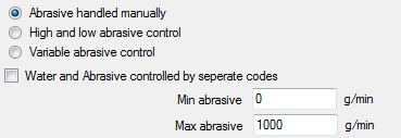
Abrasive handled manually
Check this option if the system cannot change the amount of abrasive from instructions in the CNC-file. To change amount of abrasive the machine will stop and the operator can manually adjust the abrasive.
High and low abrasive amount
Check this option if the system can switch between two different amounts of abrasive.
Variable abrasive control
Check this option if the system can handle the amount of abrasive steeples.
Water and Abrasive controlled by different codes.
Check this option if using separate M-codes for water and abrasive.
Min and Max abrasive

Enter the "minimum" and "maximum" amount of abrasive that can be used on the system.
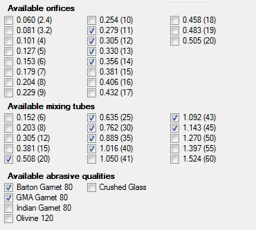
Orifices, mixing tubes and abrasive qualities
To avoid selecting unsupported equipment, check the available items in the list below.
Marking delays
This information is needed if the cutting tool is used as a marking tool.
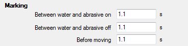
The first two values are needed only if abrasive is used for marking.
"Before moving" is a delay time between Jet On and the first move.
Pre-piercing delays
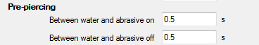
These values handle the delay between water and abrasive On/Off.
Cutting delays
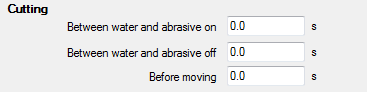
These values handle the delay between water and abrasive On/Off.
"Before moving" is the same as "minimum piercing time".
Why are there separate delays for pre-piercing and cutting?
Pre-piercing often uses other pressure and abrasive settings. For this reason it is common to use different values.
Various
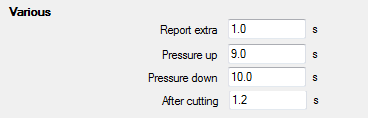
Report extra
This is extra time added to the cutting time for every marking, pre-piercing and cutting. This gives the possibility to fine-tune the estimated cutting time.
Pressure up
This is the delay time used if the pressure is increasing.
Pressure down
This is the delay time used when the pressure is decreasing.
After cutting
This is the delay time between Jet off and the rapid movement.
Pure waterjet
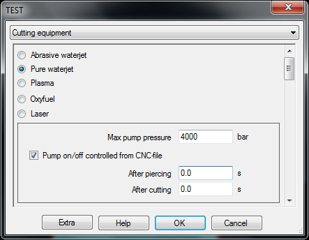
This machine type does not have as many settings.
Max pump pressure
Set the value to the highest possible on the machine.
Pump on/off controlled from CNC-file
Check this option if the system can turn the pump on/off from the CNC file. Control if this is done or not in the "Strategy".
After piercing and cutting

"After piercing" is the same as "minimum piercing time". "After cutting" is the delay time between Jet off and the rapid movement.