Linear
Shortcut "D"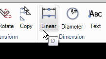
The linear dimension is used for horizontal, vertical or tilted dimensions. To enter the dimension either select an object or press the spacebar and then enter two points.
Diameter
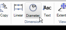
This command is used to add dimensions on circles and arc objects. Select a point on the arc or circle and place the dimension.
Text
Shortcut "SHIFT + F"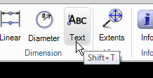
Use this command to insert text into the drawing area. Instead of selecting the start point of the text press "F" to select the font to be used.
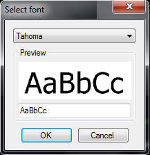
It is also possible to show a character map of all characters in actual font.
Rotated dimension

Use this command to place a dimension line that is not aligned to the measurement.
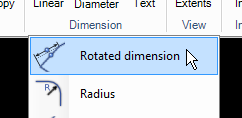
Select the angle of the dimension line and then select the object or two points.
Radius
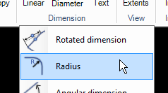
This command creates a dimension showing the Radius for an arc or circle.
Angular dimension
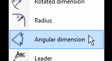
This command creates an angle dimensioning between 2 linear segments. Move the cursor before placing the dimension to select which quadrant to use.
Leader
Press "OK" to generate all parts from the drawing.
The parts are lined up by material. The final step is to use the normal "Nesting" and "CAM" commands to create the CNC file.
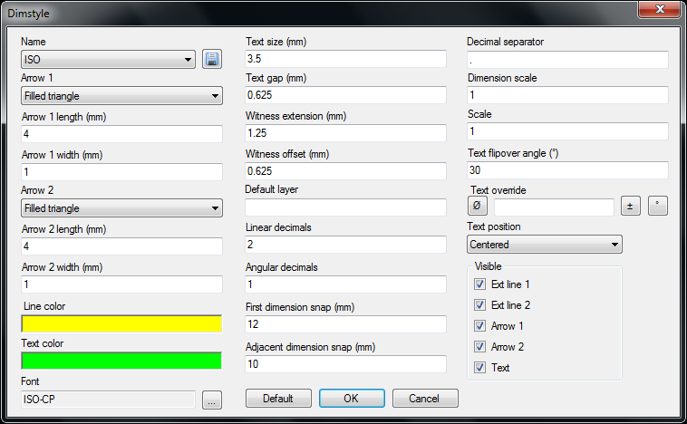
Dimension style
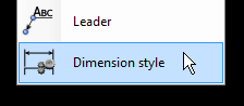
Click to show the dimension style dialog box. Read more on this command on page 56.
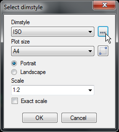
Click on the "three dot" button to set the behavior and the design of the dimensions.