Create part
Shortcut "1"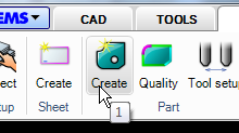
The "Create part" command creates parts from existing geometry on the screen. The parts are used to extract toolpath and are also used by the "Nesting" commands.
- Make geometries like below. The rectangle should be about 300-400 mm in X. Add the text "ABC" inside the second part.
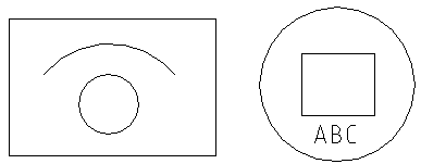
- Start the command and select all objects.

Name
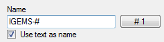
The name of the part is used by the postprocessor and the organizer and doesn't have to be unique. There are two ways of giving parts automatic names:
By increasing number
If the name includes a "#" sign then this sign will be replaced by the counter on the button. The counter will be increased by one for every new part created.
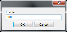
To change counter series press the button and set a new start
value. If the name is "IGEMS-#" and the counter is 1000 then the parts
will be named: IGEMS-1000, IGEMS-1001, IGEMS-1002 and so on.
Using the name of the drawing as name
If you type the sign ¤ in the name edit it will be replaced with the name of the current drawing.
By text information inside the geometry
If the checkbox "Use text as name" is activated then the actual
text will be the part name. See the "Import" command on page to read
more about how to generate names from imported files.
Add to Organizer

If a valid licence for Organizer exists this check box will be visible.
If this box is checked then all created parts will be automatically registered in Organizer.
Quantity
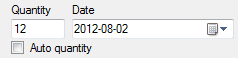
Enter the number of parts to produce. The information is used by the "Nesting" and the "Organizer". When importing a file with several identical geometries there are two choices:
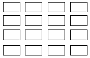
By quantity
Set the quantity to 1 and generate 16 identical parts with different names.
Auto quantity
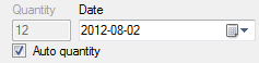
By activating the checkbox the command will count all identical parts and handle the quantity information automatically. This means that only one part with a quantity of 16 will be created when using this option. All other identical parts are deleted.
Production information
The production information is saved on the part. Change production information using the "Part properties" command. The information can be used by the "Organizer", "Applications" and the "Postprocessor".
Date
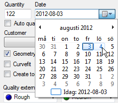
The date information is used for production date or delivery date. The information is useful if using the "Organizer" module.
Customer
Select an existing customer name in the list. Use the "plus" and "minus" button to add new and delete existing names.
Geometry
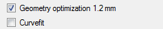
Geometry optimization
It is recommended that the "Geometry optimization" is always activated. The optimization guarantees that the toolpath created on the part is possible to cut with a tool diameter smaller than the optimization value. The value can be changed in the geometry section in the machine setting.
Curvefit
If this checkbox is activated then "Create" is performing an automatic "Curvefit" operation on the selected geometry.
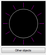
Other objects
Click the "Other objects" button to select optional objects to include in the part.
- Press the button and select the arc and the text.
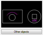
The selected objects are now included in the parts and can be used by other functions in the "2D-CAM" module.
Object located outside external geometry
To add "Other objects" that are located outside an external geometry, like in Picture 304 above, then only one part can be created at a time.
Quality settings
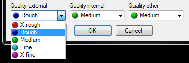
The default attaches different cutting quality to external, internal and other objects.
- Press "OK".
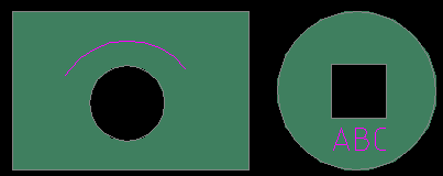
The gray color indicates that the parts are correctly described. Other commands will know what is inside and outside.